
FUSE BOX DIAGRAMS & RELAY INFORMATION
This guide covers the first-generation Infiniti QX50 (J50), including the 2014, 2015, 2016 and 2017 model years. It provides fuse box diagrams, fuse locations, amperage ratings, relay assignments and information about the vehicle’s main electrical systems.
The Infiniti QX50 is a luxury crossover SUV powered by a 3.7-liter V6 engine. The diagrams below cover the passenger compartment fuse box, engine compartment fuse boxes, fusible link block and associated relays. Some fuse and relay assignments differ between the 2014–2015 and 2016–2017 models.
Vehicle Information
- Vehicle
- Infiniti QX50
- Generation
- 1st Generation (J50)
- Model years
- 2014–2017
- Body
- 5-door crossover SUV
- Platform
- Nissan FM
- Drivetrain
- Rear-Wheel Drive (RWD) / All-Wheel Drive (AWD)
- Engine
- 3.7L V6 (VQ37VHR)
- Transmission
- 7-speed automatic
- Market
- North America and selected international markets
Passenger Compartment Fuse Box
The passenger compartment fuse box protects the airbag system, instrument cluster, BOSE audio amplifier, power outlets, blower motor, rear window defogger and other interior electrical components.
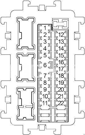
| No. | Amps | Protected circuit |
|---|---|---|
| 1 | – | Not assigned |
| 2 | 10A | Air Bag Diagnosis Sensor Unit, Occupant Classification System Control Unit |
| 3 | 10A | Headlamp Aiming Motor RH and LH, Shift Lock Relay, Automatic Speed Control Device (ASCD) Brake Switch, Intelligent Cruise Control (ICC) Brake Switch, Adaptive Front Lighting System (AFS) Control Unit, AFS Switch, Data Link Connector, LDW Switch, Sonar Control Unit, Lane Departure Warning Buzzer, Unified Meter and Air Conditioner Amplifier, Heated Seat Relay, AV Control Unit, Sonar Cancel Switch, Around View Monitor Control Unit, Buzzer, Tel Adapter Unit, Compressor, Auto Anti-Dazzling Inside Mirror, Lane Camera Unit, Stop Lamp Switch, Warning System Switch, Ionizer, Exhaust Gas / Outside Odor Detecting Sensor |
| 4 | 10A | Combination Meter, Back-Up Lamp Relay |
| 5 | – | Not assigned |
| 6 | 10A | Key Slot, Intelligent Key Warning Buzzer, Data Link Connector, Unified Meter Air Conditioner Amplifier, Rear Seatback Power Return Control, Rear Seatback Release Relay (LH), Rear Seatback Release Relay (RH), Clock, Auto Anti-Dazzling Inside Mirror, Around View Monitor Control Unit, Display Unit, Tel Adapter Unit, Satellite Radio Tuner, Daytime Running Light Relay, Combination Meter |
| 7 | 10A | Stop Lamp Switch, BCM (Body Control Module), Intelligent Cruise Control (ICC) Brake Hold Relay |
| 8 | 20A | BOSE Amplifier |
| 9 | 10A | Key Slot, Push-Button Ignition Switch |
| 10 | 10A | Seat Memory Switch, Automatic Drive Positioner Control Unit, Driver Seat Control, Door Mirror, BCM (Body Control Module) |
| 11 | 10A | Combination Meter, All Wheel Drive (AWD) Control Unit, Unified Meter Air Conditioner Amplifier |
| 12 | – | Not assigned |
| 13 | 10A | Door Mirror Defogger |
| 14 | 20A | Rear Window Defogger |
| 15 | 20A | Rear Window Defogger |
| 16 | – | Not assigned |
| 17 | – | Not assigned |
| 18 | 15A | Front Power Socket |
| 19 | 10A | Combination Meter, Unified Meter and Air Conditioner Amplifier, Display Unit, Multifunction Switch, AV Control Unit, iPod Adapter, BCM (Body Control Module), Sonar Control Unit, Tel Adapter Unit, Camera Control Unit, Door Mirror Remote Control Switch, Satellite Radio Tuner, Around View Monitor Control Unit |
| 20 | 20A | Console Power Socket (2014–2017) |
| 21 | 15A | Blower Motor |
| 22 | 15A | Blower Motor |
No matching fuses found.
Passenger Compartment Relays
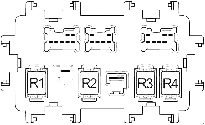
| Relay | Description |
|---|---|
| R1 | Ignition |
| R2 | Rear Window Defogger |
| R3 | Accessory |
| R4 | Front Blower |
Engine Compartment Fuse Box No. 1
Engine compartment fuse box No. 1 protects the fuel pump, engine management system, headlights, cooling fan control, air conditioning and windshield wiper circuits.
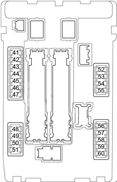
| No. | Amps | Protected circuit |
|---|---|---|
| 41 | 15A | Fuel Pump Relay |
| 42 | 10A | Cooling Fan Relay |
| 43 | 10A | Snow Mode Switch, Transmission Control Module (TCM) |
| 44 | 10A | Injectors, Engine Control Module (ECM), BCM (Body Control Module) |
| 45 | 10A | ABS, Intelligent Cruise Control (ICC) Sensor Integrated Unit, Steering Angle Sensor, Yaw Rate / Side G Sensor, Power Steering Control Unit, All Wheel Drive (AWD) Control Unit, Brake Booster Control Unit, Blind Spot Warning (BSW) Control Module, Side Radar LH/RH |
| 46 | 15A | Air Fuel Ratio Sensors, Heated Oxygen Sensors |
| 47 | 10A | Combination Switch |
| 49 | 10A | Air Conditioner Relay |
| 50 | 15A | Engine Control Module Relay (Intake Valve Timing Control Solenoid Valve, Condenser, Ignition Coils, Engine Control Module, Mass Air Flow Sensor, EVAP Canister Purge Volume Control Solenoid Valve, Exhaust Valve Timing Control Magnet Retarder, EVAP Canister Vent Control Valve, Variable Valve Event and Lift (VVEL) Control Module) |
| 51 | 15A | Throttle Control Motor Relay |
| 52 | 10A | Front Combination Lamp |
| 53 | 10A | Rear Combination Lamp, License Plate Lamp, VDC Off Switch, Adaptive Front Lighting System (AFS) Switch, LDW Switch, Combination Switch (Spiral Cable), Clock, AV Control Unit, Glove Box Lamp, Control Device, Sonar Cancel Switch, Around View Monitor Control Unit, Power Return Switch (LH and RH), Snow Mode Switch, Heated Seat Switch (Driver Side and Passenger Side), Door Mirror Remote Control Switch, Roof Module (Console Lamp), Warning System Switch, Front Power Socket, IBA Off Switch, Multifunction Switch |
| 54 | 10A | Headlamp High LH |
| 55 | 10A | Headlamp High RH |
| 56 | 15A | Headlamp Low LH |
| 57 | 15A | Headlamp Low RH |
| 58 | 10A | 2014–2015: Front Fog Lamp Relay |
| 58 | 15A | 2016–2017: Front Fog Lamp Relay |
| 59 | 10A | 2016–2017: Daytime Running Light Relay |
| 60 | 30A | Front Wiper Relay |
No matching fuses found.
Engine Compartment Fuse Box No. 2
Engine compartment fuse box No. 2 contains fuses for the horn, generator, audio system, heated seats, transmission control module, ABS and other electrical systems. The original diagrams distinguish between the 2007–2016 layout and the 2017 layout.
2014–2016 Fuse Box Diagram
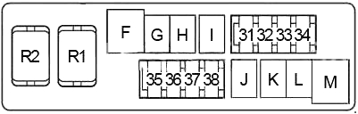
2017 Fuse Box Diagram
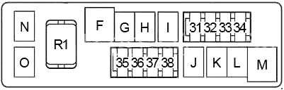
| No. | Amps | Protected circuit |
|---|---|---|
| 31 | 15A | Horn Relay, Generator |
| 32 | 30A | Rear Seatback Power Return Control, Rear Seatback Release Relay (LH), Rear Seatback Release Relay (RH) |
| 33 | 10A | All Wheel Drive (AWD) Control Unit |
| 34 | 15A | Audio, AV Control Unit, iPod Adapter, Around View Monitor Control Unit, Woofer, Camera Control Unit, Tel Adapter Unit, Satellite Radio Tuner |
| 35 | 15A | Heated Seat Relay |
| 36 | 10A | Transmission Control Module (TCM) |
| 37 | 10A | Horn Relay No. 2 (2014–2017) |
| F | 50A | Cooling Fan Relay |
| G | 30A | Ignition Relay (Fuses 2, 3, 4), IPDM E/R |
| H | 40A | Fuses 61, 63 |
| I | – | Not assigned |
| J | – | Not assigned |
| K | 40A | BCM (Body Control Module), Circuit Breaker (Automatic Drive Positioner Control Unit, Driver Seat Control, Lumbar Support Switch) |
| L | 30A | ABS |
| M | 50A | ABS |
| N | 50A | Variable Valve Event and Lift (VVEL) Actuator Motor Relay (2014–2017) |
| O | – | Not assigned (2014–2017) |
No matching fuses found.
Engine Compartment Fuse Box No. 2 – Relays
| Relay | Description |
|---|---|
| R1 | Horn |
| R2 | Shift Lock |
Engine Compartment Fuse Box No. 3
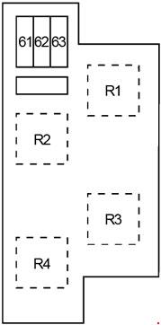
Engine compartment fuse box No. 3 is shown with separate diagrams for 2013–2015 and 2016–2017 models. The relay assignments differ between these versions.
2014–2015 Fuse Box Diagram
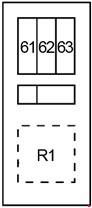
2016–2017 Fuse Box Diagram
| No. | Amps | Protected circuit |
|---|---|---|
| 61 | 10A | Accelerator Pedal Actuator |
| 62 | – | Not assigned |
| 63 | 10A | Brake Booster Control Unit |
No matching fuses found.
Engine Compartment Fuse Box No. 3 – Relays
| Relay | Model years | Description |
|---|---|---|
| R1 | 2014–2015 | Cooling Fan |
| R1 | 2016–2017 | Daytime Running Light |
| R2 | 2014–2017 | Intelligent Cruise Control (ICC) Brake Hold |
| R3 | 2014–2017 | Not assigned |
| R4 | 2014–2017 | Horn (No. 2) |
Fusible Link Block
The fusible link block protects major electrical circuits, including the generator, ignition system, headlights, blower motor and accessory circuits.
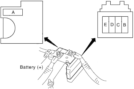
| No. | Amps | Protected circuit |
|---|---|---|
| A | 140A | Generator, Fuse B, Fuse C |
| B | 100A | Fuses F, G, K, L, M, N, 31, 32, 33, 34, 35, 36, 37, 38 |
| C | 80A | Ignition Relay (Fuses 41, 42, 43, 44, 45, 46, 47), Fuses 48, 49, 50, 51 |
| D | 60A | Headlamp High Relay (Fuses 54, 55), Headlamp Low Relay (Fuses 56, 57), Tail Lamp Relay (Fuses 52, 53), Fuses 58, 59, 60 |
| E | 80A | Accessory Relay (Fuses 18, 19, 20), Rear Window Defogger Relay (Fuses 13, 14, 15), Blower Relay (Fuses 21, 22), Fuses 6, 7, 9, 10, 11 |
No matching fuses found.
Frequently Asked Questions
Where are the fuse boxes located in the Infiniti QX50?
The first-generation Infiniti QX50 has a passenger compartment fuse box and several fuse boxes in the engine compartment. The engine compartment also contains a fusible link block that protects major electrical circuits.
Which fuse controls the cigarette lighter or power outlet?
Fuse 18 (15A) in the passenger compartment fuse box protects the front power socket. Fuse 20 (20A) protects the console power socket on 2014–2017 models.
Where is the fuel pump fuse?
Fuse 41 (15A) in engine compartment fuse box No. 1 is assigned to the fuel pump relay.
Which fuses protect the headlights?
Engine compartment fuse box No. 1 contains the headlight fuses: 54 (10A) for the left high beam, 55 (10A) for the right high beam, 56 (15A) for the left low beam and 57 (15A) for the right low beam.
Where are the blower motor fuses?
Fuses 21 and 22 (15A each) in the passenger compartment fuse box protect the blower motor. The front blower relay is identified as R4 in the passenger compartment relay diagram.
Are the fuse box diagrams identical for all 2014–2017 models?
No. The supplied diagrams identify differences between model years, including fuse 58, fuse 59, engine compartment fuse box No. 2 and the relay assignments in fuse box No. 3.
WARNING: Terminal and harness assignments for individual connectors may vary depending on vehicle equipment level, model year and market. Always check the fuse box cover and the vehicle owner’s manual before replacing a fuse. Never install a fuse with a higher amperage rating than specified.